Products
Fittings and joints
PE100 fittings from 32 mm to 1,200 mm and the jointing systems that connect them: butt fusion and electrofusion for permanent, self-restrained joints, flanges, compression fittings and saddles where a joint has to come apart.
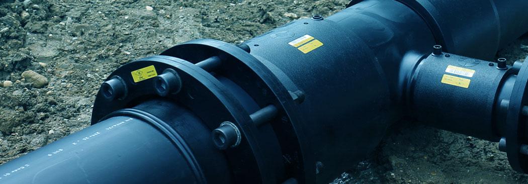
HDPE Tee
PE100 · DN110
Drag to rotate
Fittings
Standards
- Fittings
- EN 12201, ISO 4427, ES 1832
Fittings range
Sizes are outside diameters in mm. Fabricated fittings are made from pipe segments; injection fittings are moulded.
Fabricated fittings, butt fusion
| Fitting | Size range, mm |
|---|---|
| Elbow 11.25° | 110 to 1,200 |
| Elbow 22.5° | 110 to 1,200 |
| Elbow 30° | 110 to 1,200 |
| Elbow 45° | 110 to 1,200 |
| Elbow 60° | 110 to 1,200 |
| Elbow 90° | 110 to 1,200 |
| Equal tee | 110 to 1,200 |
| Reducing tee | 110 to 1,200, branch 32 to 1,000 |
Injection fittings, butt fusion
| Fitting | Size range, mm |
|---|---|
| Tee 90° | 50 to 315 |
| Reduced tee | 63 × 50 to 250 × 200 |
| Elbow 45° | 32 to 315 |
| Elbow 90° | 32 to 315 |
| End cap | 32 to 1,200 |
Adaptors, reducers and couplers
| Fitting | Size range, mm | Joining |
|---|---|---|
| Puddle flange | 50 to 1,200 | Butt fusion |
| Flange adapter, long type | 32 to 630 | Butt fusion and bolted flange |
| Flange adapter, short type | 710 to 1,200 | Butt fusion and bolted flange |
| Reducer | 50 × 32 to 1,200 × 1,000 | Butt fusion |
| Electrofusion coupler | 32 to 355 | Electrofusion |
Flanges, bolted
| Flange | PN 10, mm | PN 16, mm |
|---|---|---|
| Steel flange | 200 to 1,200 | 32 to 1,200 |
| HDPE coated steel flange | 200 to 315 | 32 to 315 |
| Blind flange, steel | 200 to 1,200 | 32 to 1,200 |
Source: ALROWAD fittings list.
Transition fittings
- PE to brass, male or female thread
- 32 mm to 90 mm
Joints
Fused joints
HDPE pipe has served municipal and industrial water networks for about 50 years. A heat-fused joint is monolithic: it carries the same pressure as the pipe and does not leak.
Jointing systems
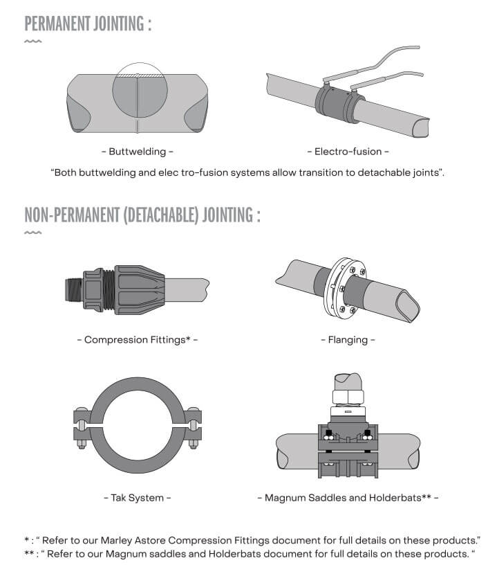
Jointing systems divide into permanent and detachable. The schematic shows the available options.
Butt fusion parameters
Pipes and fittings are butt fused to the single high-pressure procedure of ISO 21307. Heat soak time, bead size and cooling time scale with the nominal wall thickness eₙ. Pick a pipe to read the values for it.
- 20 mm
- 25 mm
- 32 mm
- 40 mm
- 50 mm
- 63 mm
- 75 mm
- 90 mm
- 110 mm
- 125 mm
- 140 mm
- 160 mm
- 180 mm
- 200 mm
- 225 mm
- 250 mm
- 280 mm
- 315 mm
- 355 mm
- 400 mm
- 450 mm
- 500 mm
- 560 mm
- 630 mm
- 710 mm
- 800 mm
- 900 mm
- 1000 mm
- 1200 mm
- SDR 41, PN 4
- SDR 26, PN 6
- SDR 21, PN 8
- SDR 17, PN 10
- SDR 13.6, PN 12.5
- SDR 11, PN 16
- SDR 9, PN 20
- Wall thickness eₙ, PE 100
- 10mm
- Minimum heat soak time
- 100 to 120s
- Minimum bead size after heating
- 2.5mm
- Minimum cooling time in the machine
- 4.3min
- Force on the pipe faces at 0.52 MPa, before drag
- 1.6kN
Gauge pressure on the machine depends on its cylinder area: convert the force with the machine maker's table, then add drag pressure.
| Phase | Parameter | Value | Unit |
|---|---|---|---|
| 1 and 2 | Heater plate temperature | 215 ± 15 | °C |
| 1 | Bead-up pressure | 0.52 ± 0.1, plus drag pressure | MPa |
| 2 | Minimum heat soak time | (11 ± 1) × eₙ | s |
| 2 | Heat soak pressure | 0 to drag pressure | MPa |
| 2 | Minimum bead size after heating | 1 + 0.15 × eₙ | mm |
| 3 | Maximum heater plate removal time | See ISO 12176-1 | s |
| 3 | Maximum time to reach fusion jointing pressure | Not specified | s |
| 4 | Fusion jointing pressure | 0.52 ± 0.1, plus drag pressure | MPa |
| 5 | Minimum cooling time in the machine under pressure | 0.43 × eₙ | min |
| 6 | Minimum cooling time out of the machine | A cooling time before rough handling may be recommended | min |
- Bead-up pressure is held until a bead shows all round the circumference of both pipe ends. The pressure is then dropped for heat soak.
- During heat soak, use the lowest pressure that keeps the pipe in contact with the heater plate, up to the current drag pressure.
- Drag pressure is the pressure needed to move the machine carriage and pipe; it is added to the bead-up and fusion jointing pressures.
Source: ISO 21307:2017, single high-pressure fusion jointing procedure, Table 3. Wall thickness from the ALROWAD PE 100 data sheet.
Documents
Next step
Other products
Pipe size range
DN63 to DN500 shown
Drag to rotate
HDPE Pipes
- 01HDPE PipesFlexible high-density polyethylene pipe for fluid and gas transfer, 16 mm to 1,200 mm in outside diameter, manufactured to DIN 8074, DIN 8075, EN 12201, ISO 4427 and ES 1832.
- 02PPH Drainage PipesPolypropylene homopolymer (PP-H) waste pipes and fittings with rubber ring sockets, for drainage inside buildings, from 32 mm to 160 mm, to EN 1451-1.